
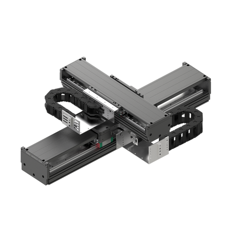
LMSSA-XY Series
Standard 2-axis cross table with cable management and optional theta axis
LMSSA Linear Motor Stages
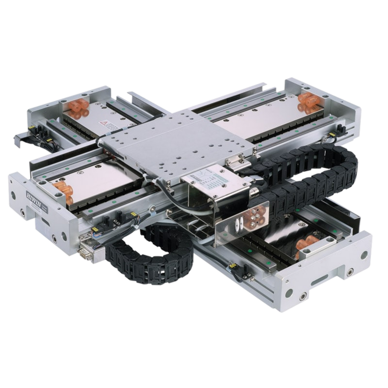
LMX1 Series Cross Tables
The linear motor stages of the LMX1 series can be combined to form cross tables. The structure of the order number shows that almost every combination of LMX1 linear motor stages is possible.
±5 arc-sec
Orthogonality of the assembled axes
±0.001 mm
Repeatability
±3 µm
Absolute accuracy after error mapping with a HIWIN drive
The standard cross table is the LMX2E: a coreless CB5 upper axis mounted across a coreless CB8 lower axis, ordered by stroke pair from the nine standard combinations in Tables 2-30 and 2-31. Encoder, limit switch, cover and cable chain codes append per the ordering diagram (G200 standard). Chapter 3 of the catalog shows customized LMX2C, LMX3C and LMX4C cross tables mixing iron-core and coreless axes.
| Model | X stroke (mm) | Y stroke (mm) | Mass without cover (kg) | Mass with cover (kg) | Configure |
|---|---|---|---|---|---|
| LMX2E-CB5-CB8-100-100 | 100 | 100 | 44 | 46 | Configure ↗ |
| LMX2E-CB5-CB8-100-200 | 100 | 200 | 46 | 48 | Configure ↗ |
| LMX2E-CB5-CB8-200-200 | 200 | 200 | 48 | 50 | Configure ↗ |
| LMX2E-CB5-CB8-100-300 | 100 | 300 | 48 | 50 | Configure ↗ |
| LMX2E-CB5-CB8-200-300 | 200 | 300 | 50 | 52 | Configure ↗ |
| LMX2E-CB5-CB8-300-300 | 300 | 300 | 52 | 54 | Configure ↗ |
| LMX2E-CB5-CB8-100-400 | 100 | 400 | 50 | 52 | Configure ↗ |
| LMX2E-CB5-CB8-200-400 | 200 | 400 | 52 | 54 | Configure ↗ |
| LMX2E-CB5-CB8-300-400 | 300 | 400 | 54 | 56 | Configure ↗ |
How a part number reads
LMX2E - CB5 - CB8 - 200 - 300 - G 2 0 0 (CB5 upper axis on CB8 lower axis, 200 x 300 mm strokes, 1 µm digital optical scales, NPN optical switches, no cover, no cable chain)
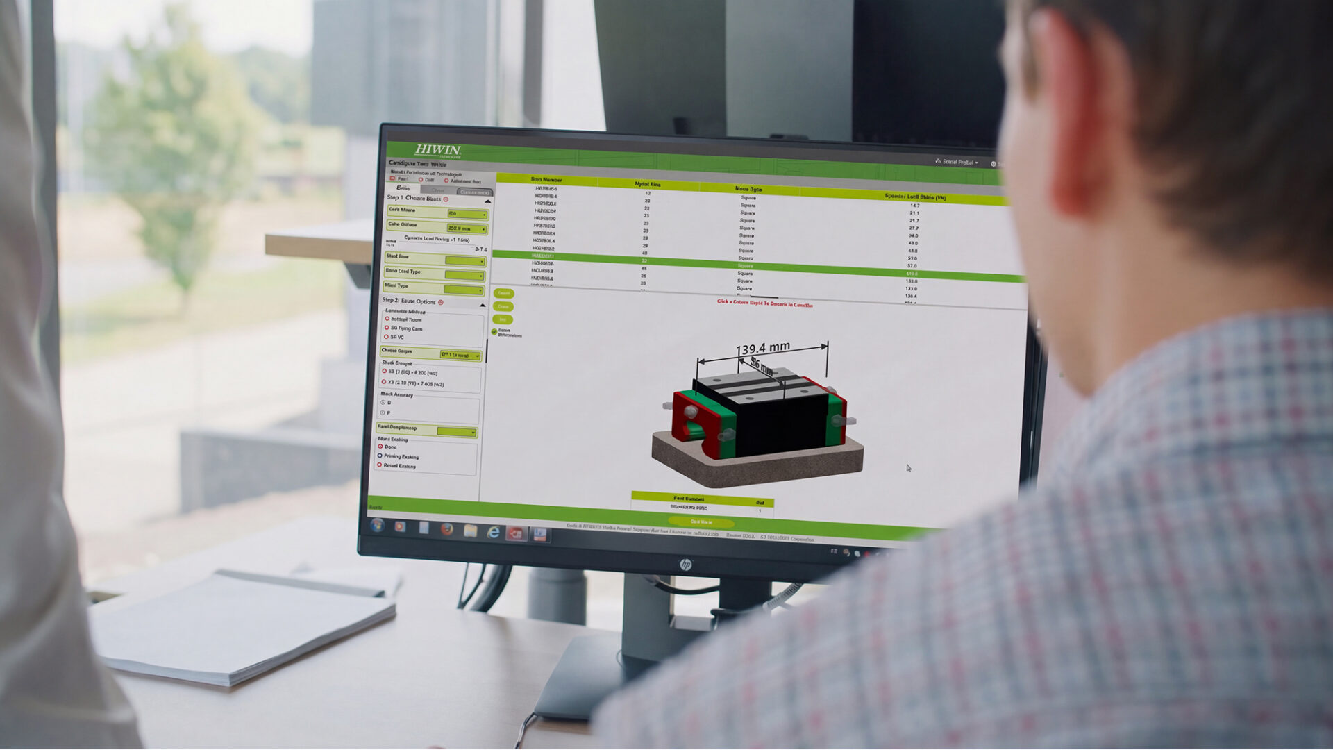
The configurator assembles this number for you, with drawings and 3D CAD. Configure ↗
Cross tables assemble from LMX1 single-axis stages; the motor family is chosen per axis.
Scale codes from the cross-table ordering diagram; G is the standard fit.
Standard 2-axis cross table with cable management and optional theta axis
LMSSA Linear Motor Stages
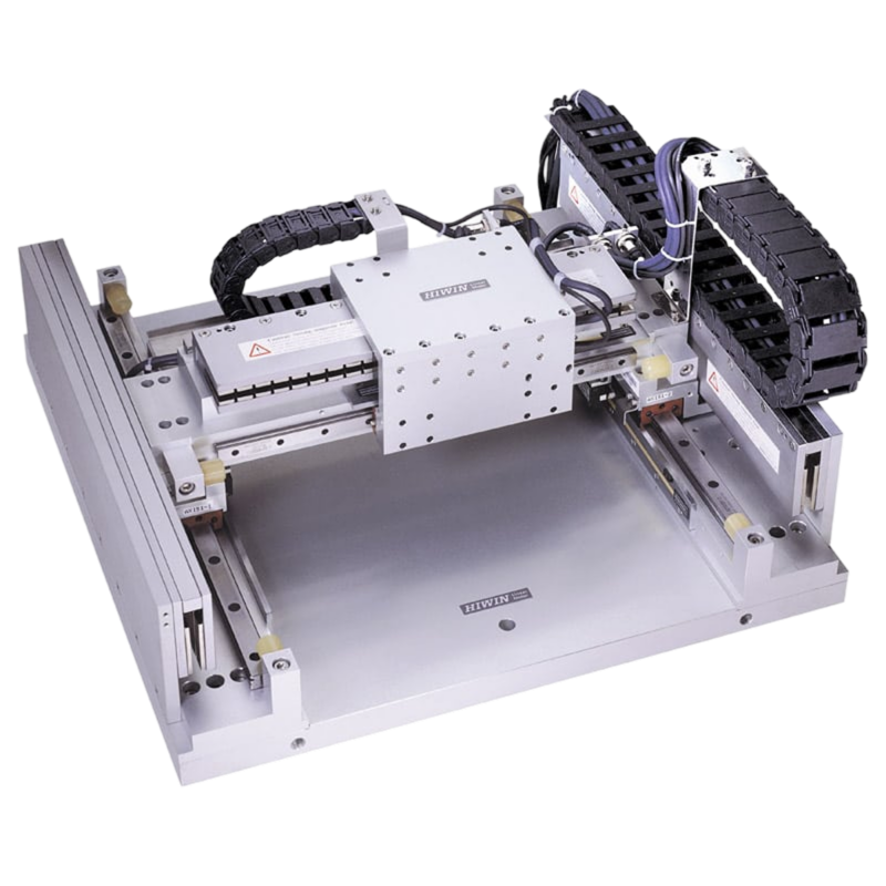
Standardized gantry system: iron-core or coreless, aluminum bridge
LMSSA Linear Motor Stages
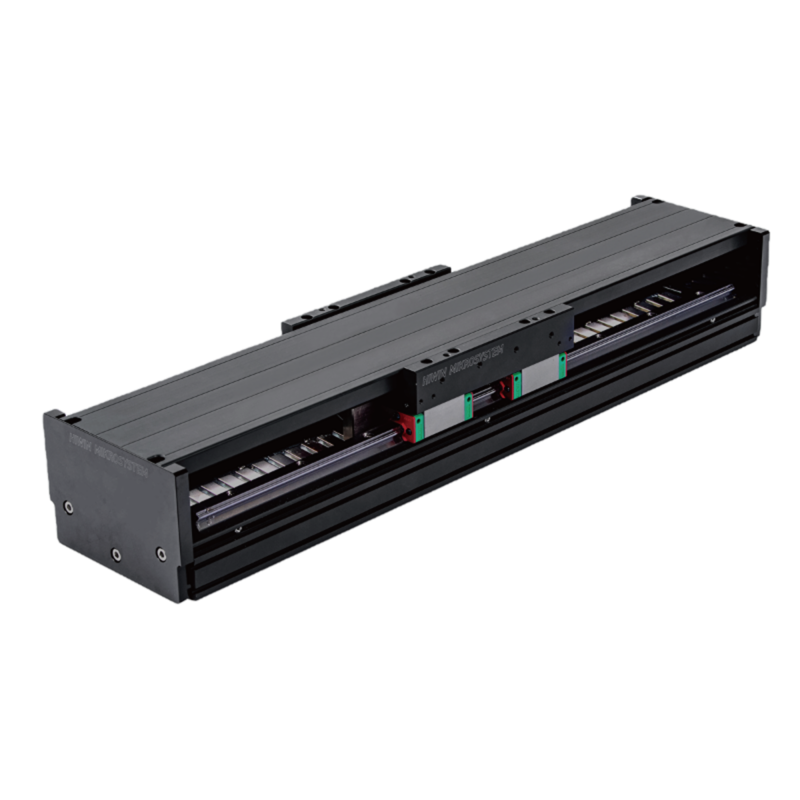
Iron-core or coreless: 5G acceleration, 0.1 µm resolution, strokes to 2,700 mm
LMSSA Linear Motor Stages
How buying works
HIWIN series are configured to your application, not bought off the shelf. Start from your loads and speeds if you are still choosing a size.
Rather talk it through? Request a quote from an application engineer.