
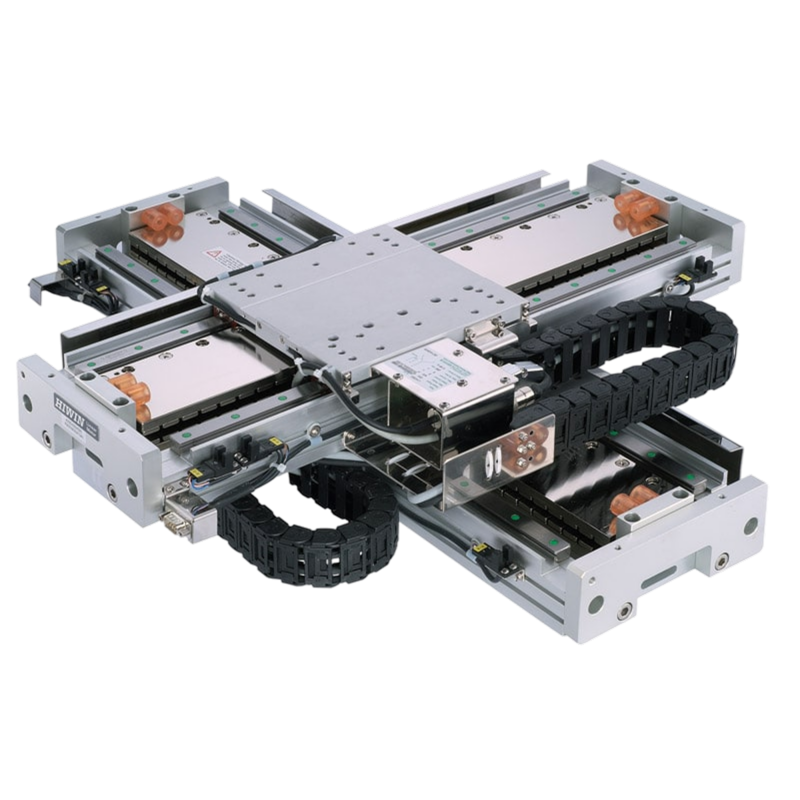
LMX1 Series
Combinable cross-table stages: ±5 arc-sec orthogonality, ±0.001 mm repeatability
LMSSA Linear Motor Stages
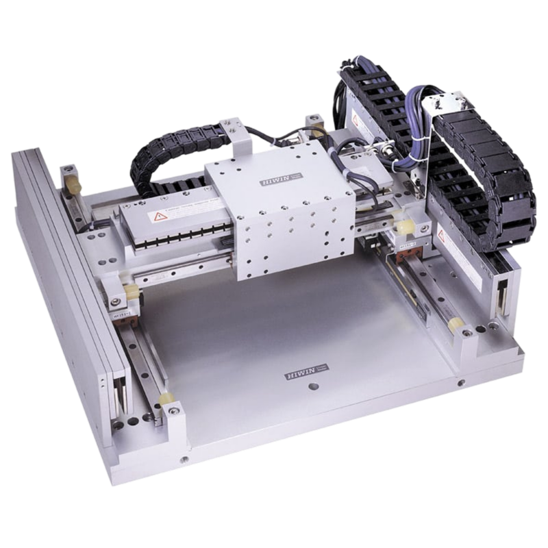
LMG2A Series Gantry Systems
The standardized gantry systems of the LMG2A series are systems with one-sided supporting guide rail. The type LMG2A-C is equipped with coreless linear motors. The type LMG2A-S is driven by iron-core linear motors. Both builds pair fast acceleration with a rigid aluminum bridge and simple assembly, holding orthogonality of ±5 arc-sec and repeatability of ±0.003/0.004 mm.
±5 arc-sec
Orthogonality between the gantry axes
±3 µm
Repeatability at 200 and 300 mm strokes
±9 µm
Absolute accuracy after error mapping, shortest strokes
The standard table pairs equal X and Y strokes on the coreless CB6/CC8 motor set; the order code also allows mixed strokes, with the lower axis from 100 mm. The LMG2A-S build swaps in iron-core motors and is quoted through HIWIN. Absolute accuracy is stated after error mapping with a HIWIN drive; resolution figures exclude the magnetic scales.
| Model | Stroke X × Y (mm) | Absolute accuracy (µm) | Repeatability (µm) | Mass (kg) | Configure |
|---|---|---|---|---|---|
| LMG2A-CB6-CC8-200-200 | 200 × 200 | ±9 | ±3 | 50 | Configure ↗ |
| LMG2A-CB6-CC8-300-300 | 300 × 300 | ±9 | ±3 | 52 | Configure ↗ |
| LMG2A-CB6-CC8-400-400 | 400 × 400 | ±12 | ±4 | 54 | Configure ↗ |
| LMG2A-CB6-CC8-500-500 | 500 × 500 | ±12 | ±4 | 54 | Configure ↗ |
| LMG2A-CB6-CC8-600-600 | 600 × 600 | ±12 | ±4 | 56 | Configure ↗ |
How a part number reads
LMG2A - CB6 - CC8 - 300 - 400 - G 2 0 0 (spaces between decoded positions)
The configurator assembles this number for you, with drawings and 3D CAD. Configure ↗
Scale options run from 40 µm analog to 20 nm digital; the standard fit is the 1 µm TTL optical scale.
Optical NPN switches are the standard fit.
The gantry ships open as standard; three cover styles protect the axes.
No chain is the standard configuration; both mounted options share a 15 × 30 mm internal space.
Combinable cross-table stages: ±5 arc-sec orthogonality, ±0.001 mm repeatability
LMSSA Linear Motor Stages
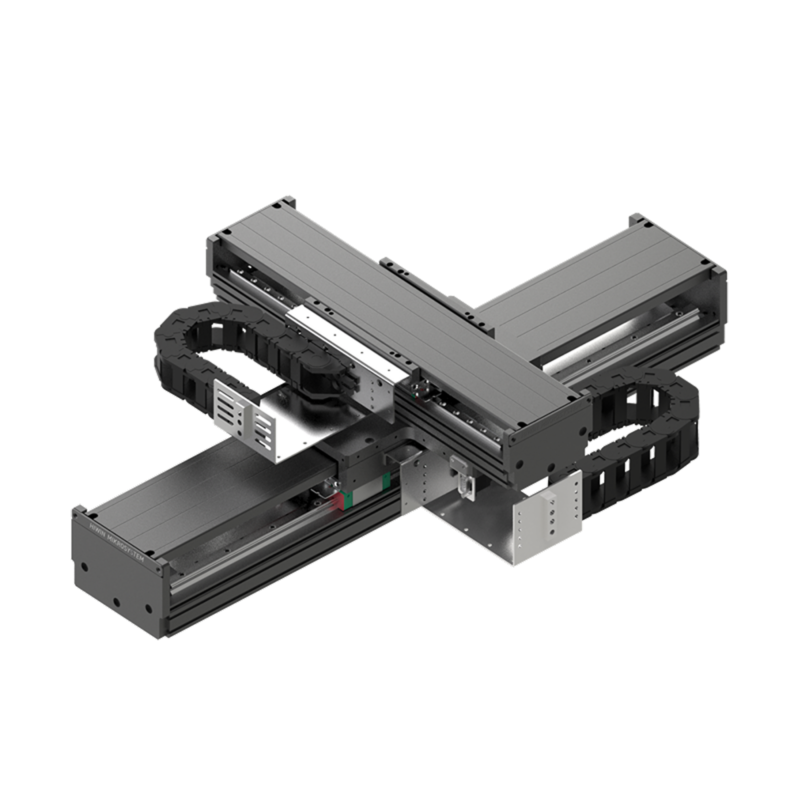
Standard 2-axis cross table with cable management and optional theta axis
LMSSA Linear Motor Stages
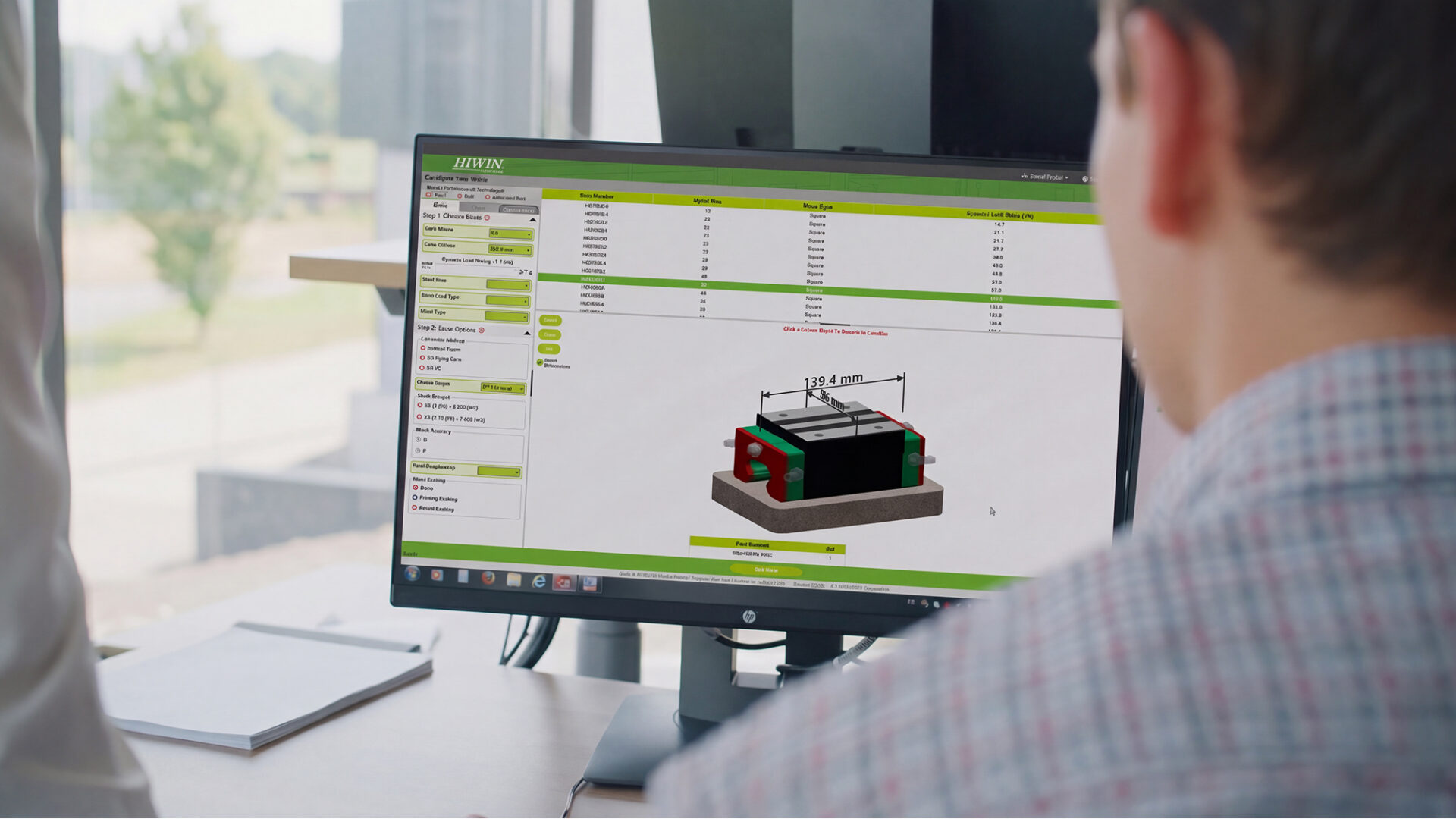
How buying works
HIWIN series are configured to your application, not bought off the shelf. Start from your loads and speeds if you are still choosing a size.
Rather talk it through? Request a quote from an application engineer.