
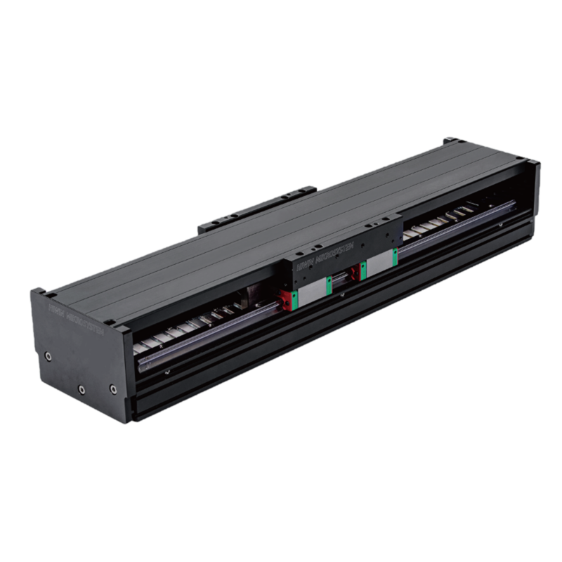
LMSSA Series
Iron-core or coreless: 5G acceleration, 0.1 µm resolution, strokes to 2,700 mm
LMSSA Linear Motor Stages
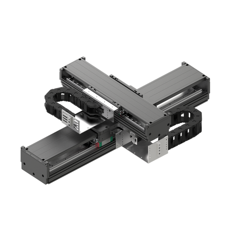
LMSSA XY Series Linear Motor XY Stages
The LMSSA XY series allows easier startup for multi-axis movement. Standard cable management options with additional space allow for easy application cable routing.
Each axis of the XY table is an LMSSA stage; start there for the single-axis spec. View LMSSA Series →
2D
Error map on the XY plane with two E series GT drives
10 arc-sec
Orthogonality over the center 200 x 200 mm stroke area
±0.5 µm
Repeatability at the best encoder grade
Each row is a standard build of one of the two catalog combinations, named upper x lower axis. The 10S100 x 13S200 (135 mm base, 185 mm height) runs 103/205 N continuous and 289/579 N peak on the upper/lower axes; the 13S200 x 20S300 (206 mm base, 200 mm height) runs 205/362 N continuous and 579/1,023 N peak. Both reach 1.5 m/s and 20 m/s², payload and encoder resolution permitting.
| Combination (upper x lower) | Stroke (mm) | Axis lengths UT x LT (mm) | Stage weight (kg) | Max payload (kg) | Configure |
|---|---|---|---|---|---|
| 10S100 x 13S200 | 200 x 200 | 450 x 550 | 28.3 | 15 | Configure ↗ |
| 10S100 x 13S200 | 250 x 250 | 500 x 600 | 29.4 | 15 | Configure ↗ |
| 10S100 x 13S200 | 300 x 300 | 550 x 650 | 30.7 | 15 | Configure ↗ |
| 10S100 x 13S200 | 350 x 350 | 600 x 700 | 32.1 | 15 | Configure ↗ |
| 10S100 x 13S200 | 400 x 400 | 650 x 750 | 33.6 | 15 | Configure ↗ |
| 10S100 x 13S200 | 400 x 450 | 650 x 800 | 34.4 | 15 | Configure ↗ |
| 10S100 x 13S200 | 400 x 500 | 650 x 850 | 35 | 15 | Configure ↗ |
| 13S200 x 20S300 | 200 x 200 | 550 x 550 | 39 | 30 | Configure ↗ |
| 13S200 x 20S300 | 250 x 250 | 600 x 600 | 40.9 | 30 | Configure ↗ |
| 13S200 x 20S300 | 300 x 300 | 650 x 650 | 42.9 | 30 | Configure ↗ |
| 13S200 x 20S300 | 350 x 350 | 700 x 700 | 44.8 | 30 | Configure ↗ |
| 13S200 x 20S300 | 400 x 400 | 750 x 750 | 46.8 | 30 | Configure ↗ |
| 13S200 x 20S300 | 400 x 450 | 750 x 800 | 47.9 | 30 | Configure ↗ |
| 13S200 x 20S300 | 400 x 500 | 750 x 850 | 49.1 | 30 | Configure ↗ |
How a part number reads
LMSSA2X - 10S100 - 13S200 - 200 - 200 - K A S 0 A 0 (upper axis 10S at 100 N, lower 13S at 200 N, 200 x 200 mm stroke)
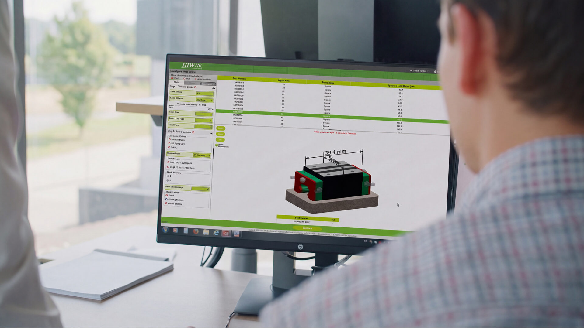
The configurator assembles this number for you, with drawings and 3D CAD. Configure ↗
Repeatability and accuracy follow the encoder grade; the catalog's three figures map to the three encoders in order.
One digit in the model number; the chain carries spare space for application cables.
Iron-core or coreless: 5G acceleration, 0.1 µm resolution, strokes to 2,700 mm
LMSSA Linear Motor Stages
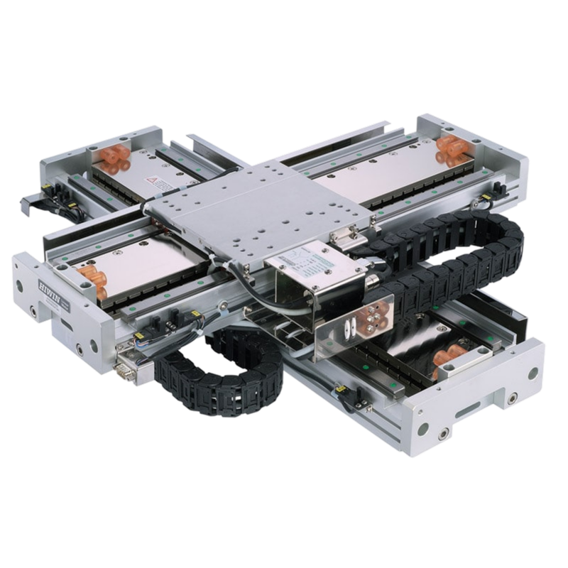
Combinable cross-table stages: ±5 arc-sec orthogonality, ±0.001 mm repeatability
LMSSA Linear Motor Stages
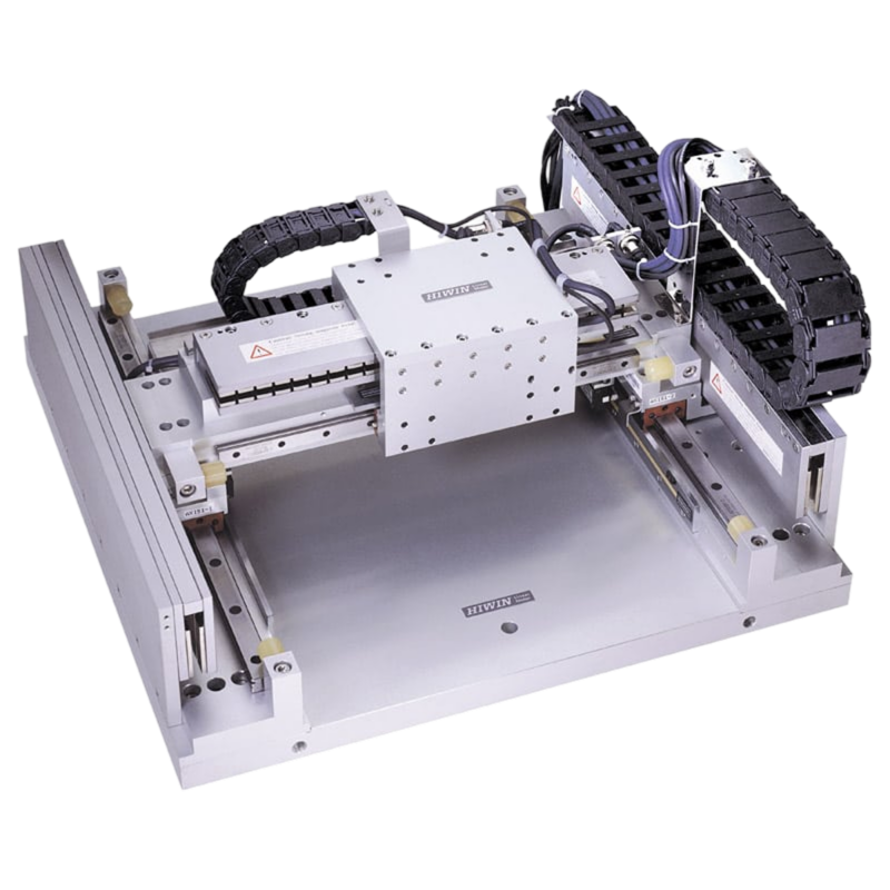
Standardized gantry system: iron-core or coreless, aluminum bridge
LMSSA Linear Motor Stages
How buying works
HIWIN series are configured to your application, not bought off the shelf. Start from your loads and speeds if you are still choosing a size.
Rather talk it through? Request a quote from an application engineer.