
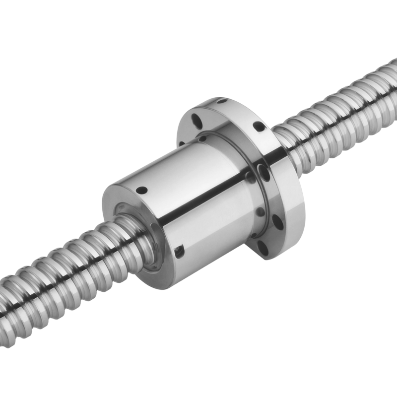
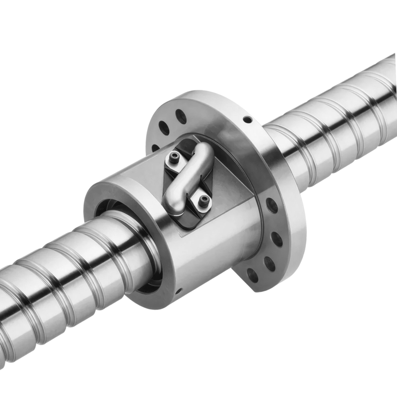
Super T Series
Super T Series Ballscrews
- Nut Configurations
- FST (single nut), FDT (double nut)
- Nominal Diameter
- 8 - 80 mm
- Lead
- 3 - 40 mm
- Accuracy Grade
- JIS C0 - C7 (ground), C6 - C10 (rolled)
The Super T series circulation path has the elements leaving the ball track tangential to the PCD and coordinating with the lead angle of the ballscrew shafting. This optimal design not only reduces the noise level but also vibrations leading to smoother rotation.
-
3–5 dB
Quieter than general-series nuts across the speed range
-
23,361 kgf
Max dynamic load C in the FST tables (R80-16B3)
Applications
- CNC machinery
- Precision machine tools
- Industrial machinery
- Electrical machinery
- High speed machinery
Nut configurations
In the nut code, F is the flange end, S or D marks a single or double nut, and T is the Super T circulation. The ground FST and FDT share the same size matrix in the precision ground tables; the FDT adds a preload spacer between its two nuts. The rolled FST single nut is cataloged as a standard product in 41 sizes from R8-3A1 to R55-10B2 (8–55 mm diameter, 3–25 mm lead).
| Model | Execution | Nut | Circulation | Configure |
|---|---|---|---|---|
| FST | Precision ground | Single, flange | Tangential recirculation plate | Configure ↗ |
| FDT | Precision ground | Double, flange | Tangential recirculation plate | Configure ↗ |
| FST | Rolled | Single, flange | Tangential recirculation plate | Configure ↗ |
Part numbers & options
How a part number reads
1R40 - 10B2 - PFDWE2 - 800 - 1000 - 0.0035 - M (catalog ch 5 example; a Super T nut carries T in the circulation position, e.g. FST or FDT)
- 1
- Start type — 1 single · 2 double · 3 triple · 4 four · 5 five start
- R
- Right hand screw
- 40
- Nominal diameter (mm)
- 10
- Lead (mm)
- B2
- Number of turns — A 1.6 · B 2.6 · C 3.6, suffix = loops (B2 = 2.6×2)
- P
- Preload type — P compression · O offset
- Q
- Nut start type, high-lead nuts only — D double · T triple · Q quaternary · F five start
- F
- Nut shape — S square · R round · F nut with flange
- D
- Nut type — S single nut · D double nut
- W
- Circulation type — V tubes above nut body · W tubes within nut body · B bonded tube · I internal cap · H end cap · C Super S · T Super T · P/S RD series
- E2
- Optional functions — E2 self-lubrication · R1 rotating nut · C1/C2 cool type · Q1 spacer
- 800
- Thread length (mm)
- 1000
- Total length (mm)
- 0.0035
- Lead deviation in random 300 mm travel
- M
- Note — D biaxial movement · M stainless · H hollow shaft · L heavy load
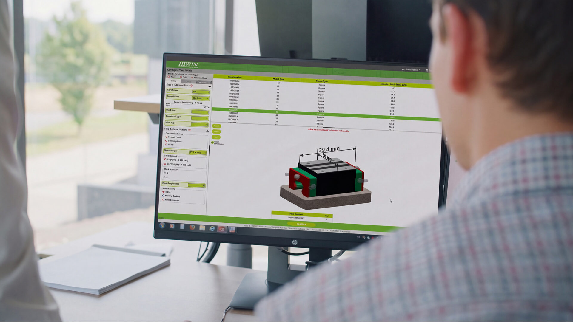
The configurator assembles this number for you, with drawings and 3D CAD. Configure ↗
Accuracy grades
Precision ground ballscrews are graded by lead variation over any 300 mm of travel (V300p, Table 4.3). HIWIN precision ground ballscrews are available in JIS grades C0 to C7. The rolled FST runs C6 to C10.
- C0 V300p 3.5 µm — The tightest grade: jig borers, precision measurement and lathe X axes.
- C1 V300p 5 µm — High-precision positioning axes on machine tools.
- C2 V300p 6 µm — Machining center and milling machine feed axes.
- C3 V300p 8 µm — The common CNC machine tool grade across X, Y and Z axes.
- C4 V300p 12 µm — General machine tool axes with moderate positioning demands.
- C5 V300p 18 µm — Positioning work where efficiency matters more than fine accuracy.
- C6 V300p 23 µm — Transfer and general automation axes.
- C7 V300p 50 µm — Transport-grade motion; also the entry grade for rolled ballscrews.
Preload methods
Preload eliminates the clearance backlash between ball and track (ch 4.4). Maximum preload for CNC machine tools should not exceed 8% of the basic dynamic load C.
- Double nut Spacer between two nuts — The FDT arrangement. An oversize spacer gives tension preload, the standard for precision ballscrews; compression preload is available on request.
- Oversized ball Single nut, four-point contact — Balls slightly larger than the groove space preload a single nut such as the FST without added length.
- O Offset pitch, single nut — A ground offset on the center pitch replaces the double nut: compact and stiff at small preload forces, but not for heavy preloading (keep below 5% of C).
Optional functions
Appended to the nut code (ch 5 specification illustration).
- E2 Self-lubrication — Built-in lubrication unit on the nut.
- R1 Rotating nut — Nut-rotating drive for long-stroke axes.
- C1, C2 Cool type — Cooling provisions for thermally sensitive axes.
- Q1 Spacer — Spacer elements between balls.
Shaft and material options
Suffix codes from the ordering diagram. Right hand thread is standard; left hand thread and longer lengths are available upon request.
- M Stainless steel — Available upon request; contact a HIWIN engineer.
- H Hollow shaft — Supports through-shaft lubrication and cooling layouts (Fig 4.33).
- D Biaxial movement
- L Heavy load — Heavy load series shafting (catalog ch 8.4).
Other Ballscrews & Supports
-
-
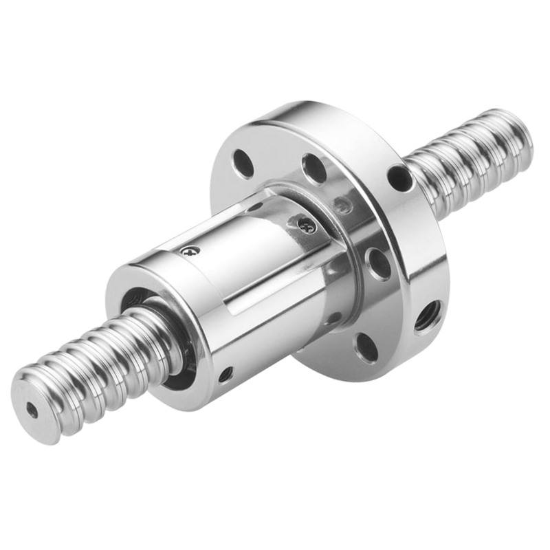
Super Z Series
High-Speed Low-Noise Ballscrew with Cassette-Type Circulation
Ballscrews & Supports
-
How buying works
Spec it in the configurator: drawings, 3D CAD, and a quote to follow.
HIWIN series are configured to your application, not bought off the shelf. Start from your loads and speeds if you are still choosing a size.
Rather talk it through? Request a quote from an application engineer.